On directional drilling technology
Among a few rules of thumb, our guidelines for planning contain the most important parameters of our machinery, providing a manual for designers in the early phases of their project.
.Directional drilling does require a launching and receiving mud pit for collecting the drilling slurry added throughout the drilling. In case this is negligible, for example due to the characteristics of the work area, the pits are not necessary.
Rocket drilling requires a receiving pit in all cases. These must be dug as deep as the drilling depth through the intersecting object. Work pits shall be provided by the client.
Guidelines for Planning – For directional drilling
Initial position, applicable machinery, factors to consider due to measurements technologies and the general geometry of drills, and other aspects to consider
Guidelines for Planning for directional drilling
I. Initial position
Determining the estimated length.
Determining the overall diameter of the pipe or pipes to be installed; material of the pipes
Estimated length: the distance between the two furthermost points of the section to be crossed by the drilling. Overall diameter of the pipe or pipes to be installed: the diameter of the circle we can draw around pipes installed jointly, plus 20%.
The material of the pipes is typically CPE or steel.
II. Applicable machinery
Based on the following table, the applicable drill can be selected for the initial position and the minimum inflection radius can be determined; as per this value, as well as the parameters of measuring (see III.) the actual drilling length can be calculated. (The resulting length compared with the estimated length in the initial preconditions may alter the selected drill!) In case the pipe to be installed is made of CPE, the typical radius of the arc of the drill equals the minimum inflection radius of the drill shanks; in case we are laying a steel pipe, the typical radius is the radius of the self-inflection arc of the steel pipe! If this measurement is unknown, but we still need to start planning, we’d do well to multiply the pipe diameter (mm) by 1000 and take the result (m) as the drilling arc. This is of course a measurement for the combined arc, meaning that if the drill moves forward both in a horizontal and vertical arc, the two projections must be considerably larger. In case of insulated steel pipes with exceptionally large diameter and thick walls, the multiplying factor may even reach 1300.
The most important drilling parameters of our machinery:
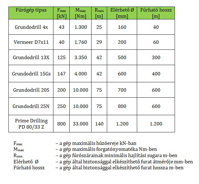
Elérhető Ø [mm] - Available Ø
Fúrógép típus - Drill type
Fúrható hossz [m] - Length drilled
F-max – the machine’s maximum traction force in kN
M-max – the machine’s maximum torque in Nm
R –min – the minimum inflection radius of the drilling shanks in metres
Available diameter – diameter of the borehole in mm that the machine can safely attain
Length drilled - length of the borehole in metres that the machine can safely attain
III. Factors to consider due to measurements technologies and the general geometry of drills
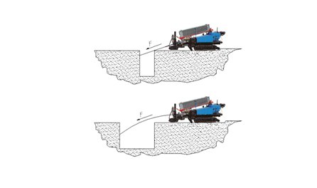
The inclination of the angle with the horizontal for directional drills in drilling positions should not exceed 17 - 19°, that is 30–35%. This is the maximum initial angle for drilling. The most wide-spread measuring method (used by Zolmat as well) can measure the inclination to the vertical for the probe placed in the drill bit up to 45° (100 %). This is the maximum arriving angle of the drilling. The drill cannot arrive in a sharper slope than this – a lower steep is naturally possible. Due to the limits of the measurement technology, the lowest point of drilling measured from the surface is 12-15 m. (Depending on active and passive interference.)
The axis of the drilling can be calculated from arcs and straight sections in accordance with the minimum inflection radius, the maximum initial and final angles, and the maximum depth of drilling.
IV. Other aspects to consider
Utilities: If the circumstance regarding public utilities are uncertain, the duration of the drilling may considerably alter compared to the planned timeframe. (it is often the case that field measurements show that public utilities are not where they are supposed to be, in which case we must deviate from plan.)
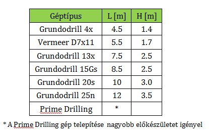
Space requirement: Depending on the type of machinery, the installation of the drill and performing the directional drilling requires a free working area of at least L length and H width along the axis of the drilling. When choosing the launching area, we must consider that pulley anchors or picket columns must be driven into the ground to a depth of 1m in order to fix the machine.
In the vicinity of the installed drill, further areas must be provided for the truck transporting the betonite mixing equipment (curb weight: 12-20t). The truck should be parked as near to the drill as possible and not farther than 50 metres, considering the protection of the betonite hose and control cable, which are connected to the betonite slurry mixes and the drill.
The space requirements of the inserted pipe or pipes may also be a considerable factor since for example an intercrossing cannot be constructed if the receiving end has no space for an outstretched pipe. In case the inserted pipes need welding in the working area, adequate space should also be provided for this activity.
Soilwork: Research pits may be needed if the placement of public utilities is not known precisely; moreover, launching and target mud pits may be necessary to collect the used slurry.
Pits: Their placement should not obstruct drilling. The launch-side pit should not be too long because if several metres of drilling shank is “hanging” in the air, their forward thrust can easily result in their outward bending in lack of support from the sides. This means that the drill’s thrust is not fully utilized because it only inflects the shanks.
Calculating the pit size: V = V borehole* n * m
ahol:
k - a factor depending on soil compression
n - a factor depending on the shear strength of the soil
m - a factor depending on the water content of the soil
No precise research has taken place in this respect. According to experiences, the usual numbers are:
- for clay soils: k * n * m ~ 2 - 5
- for sand: k * n * m ~ 1 - 2
Have we missed something?
If you have further question, please do not hesitate to contact us. Our colleagues will get back to you ASAP.